 |
|


|
|
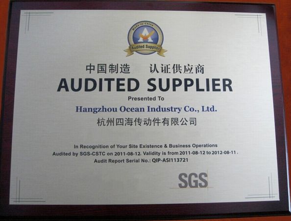
Certification

- I'm Online Chat Now
Company News
Gear Design Guide: Why the Small Pinion Wears Faster Than the Large Gear (Hardness Matching Is Often Neglected)
Workshops frequently encounter this issue: a gear reducer fails within half a year. Teeth surfaces are covered with pitting, and some teeth are fractured. Many designers only select module based on experience and casually specify Grade 8 precision. After disassembly and inspection, excessive center distance deviation and insufficient tooth surface hardness are found.
Gear transmission seems simple — just two meshing gears. But in practical operation, troubles emerge constantly: spur gear or helical gear? What precision class should be adopted? What tooth surface hardness is required? What causes pitting and tooth breakage?
Numerous engineers pick modules arbitrarily, set precision without careful consideration, and simply adopt 45 steel because it is widely used. Only after abnormal heating, noise, pitting or tooth fracture occurs do they realize proper calculation was skipped during selection.
This guide covers five core design points without complicated strength formulas, focusing on selection criteria and underlying logic.
1. Understand Gear Failure Modes First
Design priorities vary for different failure types. Misjudging failure modes leads to wrong selection. Four common failure modes are listed below:
- Tooth surface pitting: The most typical failure for enclosed gear drives. Repeated contact stress generates tiny surface cracks, which expand and peel off to form pits. Symptoms include iron debris in lubricant, increased noise and vibration.
- Tooth surface wear: Dominant in open gear drives. Dust and contaminants enter the meshing zone and abrade tooth profiles. Teeth become thinner, and backlash gradually increases.
- Tooth breakage: Fatigue fracture at the tooth root or overload fracture. It is the most destructive failure and will disable the whole transmission system.
- Scuffing: Occurs under high speed and heavy load. Instant high temperature breaks the lubrication film, and metal surfaces weld and tear, leaving sliding scratches on tooth flanks.
Design principles: Enclosed drives mainly resist pitting, so high tooth surface hardness is required. Open drives focus on wear resistance, and soft tooth surfaces are reserved for wear allowance. Heavy-load transmissions prioritize tooth root strength to avoid breakage.
2. Spur Gear / Helical Gear / Bevel Gear — Application Scenarios
Three widely used gear types in mechanical design:
- Spur cylindrical gear: Simple structure, low manufacturing cost and no axial thrust. Drawbacks include meshing impact and noise, not suitable for high-speed operation. Suitable for low-to-medium speed, heavy-duty and non-critical transmissions, such as ordinary reducers, conveyors and machine tool feed mechanisms.
- Helical cylindrical gear: Teeth engage gradually, delivering smooth transmission, low noise and higher load capacity than spur gears of the same size. Axial thrust is generated, so thrust bearings are mandatory. Ideal for high-speed, heavy-duty applications requiring stable running, for example automotive gearboxes and precision machine tool spindle drives.
- Straight bevel gear: Used for intersecting shafts, normally at a 90° angle. It changes power transmission direction, applied in reducer steering units and machine tool headstocks.
Practical selection rule: Spur gears for low-speed general transmission; helical gears for high-speed smooth operation; bevel gears for direction change.
A common pitfall: A larger helix angle improves contact ratio and smoothness, yet amplifies axial force. The recommended helix angle range is 8°~15°. Excessively large angles overload bearings.
3. Gear Precision Class — Do Not Directly Specify Class 6
Gear precision ranges from Class 0 to Class 12. Smaller numbers represent higher precision and higher processing cost. Many engineers blindly specify Class 6 or Class 5, raising cost sharply without necessary performance gain.
Precision selection depends on peripheral speed, noise requirement and rotational accuracy:
- Class 8: General grade, applicable to most low-speed transmissions in general machinery, including standard reducers, conveyors and cranes.
- Class 7: Medium precision, for machine tool gearboxes and medium-speed reducers where rotating speed and noise are controlled.
- Class 6 and above: Reserved for high-precision spindle units, automotive transmissions and precision instruments, rarely needed for ordinary machinery.
Rule: Choose Class 8 if acceptable; upgrade to Class 7 only when necessary; Class 6+ is overkill for standard conveyors. Supporting components such as shafts and bearings must match gear precision. A high-precision gear paired with low-precision shafts still runs with runout.
4. Gear Material & Heat Treatment — The Core of Proper Selection
Many designers use 45 steel by convention without evaluating working conditions.
- 45 steel normalized or quenched and tempered: HB170~230, soft tooth surface. For low-speed, light-load and non-critical applications such as open gears and low-speed stages of simple reducers, low cost and easy machining.
- 45 steel surface quenching: HRC40~50, hard tooth surface. Suitable for medium speed and medium load with moderate wear resistance. Hard surface with tough core withstands light shock.
- 40Cr quenched and tempered + surface quenching: HRC48~55, better hardenability and higher load capacity than 45 steel, adopted for important medium-load gears.
- 20CrMnTi carburizing and quenching: HRC58~62, hard tooth surface with excellent core toughness. Used for heavy-load, high-speed, shock-resistant key gears like automotive transmissions and high-speed stages of reducers.
Rule summary: Soft tooth surfaces for open drives and non-critical occasions; hard tooth surfaces for enclosed heavy-load drives.
Key hardness matching rule: The pinion meshes more frequently than the larger gear. The hardness of the pinion should be 5~10 HRC higher than the mating big gear for uniform wear. If paired gears adopt identical material and hardness, the pinion will wear out prematurely.
5. Lubrication and Sealing
Poor lubrication and sealing cause overheating, abnormal noise and early gear failure. Lubrication selection follows peripheral speed:
- Low speed (v<2 m/s): Grease lubrication, simple structure and low sealing requirement, widely used for open gears and low-speed reducers.
- Medium speed (2 m/s<v<12 m/s): Oil bath lubrication, the mainstream solution for enclosed reducers.
- High speed (v>12 m/s): Force-feed spray lubrication. Oil bath will cause excessive churning loss and temperature rise at high speed.
Sealing selection: Grease seals for low speed, oil seals for high speed, and dust covers for dusty environments.
Experience tip: The oil level in enclosed reducers should just submerge one tooth height of the large gear. Overfilling oil increases churning loss and temperature; insufficient oil leads to inadequate lubrication.
Conclusion
Gear selection logic is straightforward: Match design direction to failure modes, and select gear type, precision and material according to working conditions.
- Enclosed drives guard against pitting with hard tooth surfaces; open drives use soft tooth surfaces reserved for wear; heavy-load drives enhance tooth root strength against fracture.
- Spur gears for low-speed general transmission, helical gears for smooth high-speed operation, bevel gears for power direction change.
- Avoid over-specifying precision: Class 8 satisfies most general transmission demands.
- Material selection: 45 steel for non-critical light loads, 40Cr quenched gears for medium loads, carburizing steel for heavy shock high-speed applications.
- Lubrication by speed: grease for low speed, oil bath for medium speed, spray lubrication for high speed; never overfill reducer oil.
Seasoned engineers make fast gear selections not because they memorize complex formulas, but because they clearly know the load, rotating speed and operating environment of the gear. Once you understand the rationale behind each parameter, proper selection becomes easy.
Pub Time : 2026-11-09 11:05:23
>> News list
Contact Details
Hangzhou Ocean Industry Co.,Ltd
Contact Person: Mrs. Lily Mao
Tel: 008613588811830
Fax: 86-571-88844378